It is essential that this 2G™ rigid core product is installed in accordance with these instructions as well as the applicable national standards and building codes for the installation of resilient flooring at the time of installation, to ensure a quality fit. Prior to installation, please check that this product is suited to the end use application. If in doubt, please contact your supplier.
This product is a floating floor with excellent acoustic, thermal and waterproof properties made rigid to assist installation over uneven subfloor surfaces. It will not absorb, swell or be damaged by water. When installed properly and under normal use, damp mopping and topical spills cleaned up promptly will not harm the performance of the floor. This product is not suitable for installation outdoors nor in rooms that will be continually wet. It is suitable for use in traditional residential bathrooms, kitchens, laundry/utility rooms.
Install permanent fixtures prior to installation of this product, leaving a space for expansion and contraction; see below. Please refer to section Installation procedure as to when sealant is permitted in expansion gaps.
A separate underlay is not normally recommended; refer to floor covering supplier for details.
National standards and building codes- European Union: DTU 53.2, DIN 18365 (Teil C)
- United Kingdom: BS 8203
For commercial installations make sure flooring materials are removed from packaging at least 48 hours prior to installation (planks/tiles may be stacked but must be rested flat) and allowed to condition in the room where the installation is to take place. Room temperature must be kept between 18-27°C.
For residential installations acclimatisation is generally not essential if the product temperature is already in the range 18-27°C but if the product has been exposed to extreme temperatures prior to installation, acclimatisation is required.

Before this product may be installed, all subfloors should be solid and sound, smooth and level, clean and swept free of all debris.
Any unevenness in the subfloor should be limited to a maximum of 3mm below the level for 2m in any direction.
Any isolated highpoints/ridges should first be removed to avoid damage to the product. Larger differences in height may need to be levelled out by filling the entire surface of the floor. Additional guidance on subfloor preparation is provided by the national standards and building codes for the installation of resilient flooring noted on 'General information'. If in doubt, please contact your supplier
- Hygrometer test = less than 95% RH.
- Calcium carbide test = no more than 3% for cementitious screed / no more than 1.4% for calcium sulphate screed.
The design on this product is randomly distributed and can be heavier on some tiles/planks than others. To prevent heavy and light colour shading areas, the tiles/planks should be unboxed and shuffled.
For detailed installation steps please see installation steps
NOTE: Rigid core/hybrid flooring should be protected from heat and/or prolonged exposure to direct sunlight as this may cause damage to your floor. See section Sunrooms / conservatories / 3 season rooms.
This product should be installed with a minimum expansion gap of 5 mm around the perimeter of the room and all fixed objects, including pipes. This minimum must be increased to 8 mm for areas larger than 100 m² (consult your supplier for larger areas). Note: the minimum expansion gap is defined as the smallest gap between product and static fixture, that can be measured at ANY point around the perimeter.
To allow for thermal expansion, door frames should either be undercut, or an expansion gap left. Skirting should either be removed or undercut. Alternatively, a suitable edge trim should be used to cover the expansion gap. Mouldings or skirtings installed post floor installation should be fixed to the wall and NOT to the floor covering, leaving a 0.5mm clearance between these and the floor surface.
In potential wet areas where it is necessary to protect the expansion gap between fixed furniture and the flooring product from potential water exposure, a flexible acrylic or flexible low modulus neutral cure silicone sealant may be used. Sealant should not be used for the general filling of expansion gaps.
The potential wet area is to be isolated from the main field using an expansion joint system or similar at door junctions. NOTE: As a guide we recommend a maximum net sealed area of 4 m². For larger areas please consult your supplier.
Where the flooring run exceeds 15 m in width or length, a 8 mm expansion joint should be used and repeated thereafter.
This product should always be installed with staggered joints:
- Planks with a minimum 200 mm between short ends
- Tiles as a ‘brick pattern (off-set)
Such that four corners never meet. Refer to 'Installation steps' Fig.3a / 3b
Special care must be taken when installing this product in rooms that are exposed to large temperature fluctuations e.g. unheated rooms, sunrooms/conservatories or direct sun through glass doors, as incorrect use of expansion gaps can cause damage. In these cases, a minimum 10mm expansion gap should be used.
This product is not suited to use in saunas/similar. Floors should be adequately protected in the vicinity of stoves/open fireplaces.
- Concrete/Screed: Where the subfloor is uneven an appropriate smoothing compound should be selected.
- Quarry Tiles/Mosaics/Terrazzo/Ceramics: Ensure the surface is firm, dry and free of wax, oil and dust particles. Fix any loose tiles. Level any grout lines with a width and/or depth of more than 5 mm.
- Timber Floors: These should be solid with minimal flexibility. All loose boards must be firmly fastened, gaps filled and undulations removed. Where necessary, overlay floorboards with flooring grade plywood or similar.
- Woodblock/Parquet Floors: Make sure these floors are solid and fix any loose or broken areas. Wood block floors laid direct to earth/bitumen/pitch must be removed prior to installation.
- Metal and Painted Floors: Remove any loose paint or other finishes.
- Linoleum/Thermoplastic/Vinyl/Cork: Make sure these floors are solid and fix any loose or broken areas.
- Any existing floors installed with asphaltic tile adhesive (ATA or ‘Cutback’) must first be suitably covered/encapsulated or mechanically removed.
- Textile floor coverings (including carpet) must be removed.
- Laminate: It is normally recommended that this is uplifted.
- Asbestos: Some older resilient tiles and adhesives can contain asbestos. Asbestos and asbestos adhesive residue must be mechanically abated by a professional abatement company prior to installing any LVT. In case of doubt contact the relevant authority for advice on removal and disposal.
- Other Floors: Consult your supplier.
Underfloor Heating: It is possible to install this product over floors incorporating underfloor heating, but these must be controlled to keep the temperature at the interface between the backing and subfloor surface at no more than 27°C.
Electrical Underfloor Heating: Please consult manufacturer to ensure their system is compatible with this flooring. Mesh / wire systems must be bedded into a base coat of appropriate primer & levelling compound to cover the wires or mesh by consulting your underlayment supplier.
NOTE: Underfloor heating may affect moisture levels. Consult your supplier for details.
- Regularly sweep the floor to remove loose dirt or grit as these can cause fine scratches.
- For a thorough clean, a range of pH neutral cleaning products are available (‘Clean’, ‘Remove’ & ‘Refresh’). Avoid the use of regular household cleaners and bleachbased detergents. These could make the floor slippery or cause discolouration.
- Always mop up spills as soon as possible, to reduce the risk of slipping and possible staining.
- Use entrance mats to protect against grit and moisture.
- Ensure mats and rugs are of non-staining variety (not rubberbacked) to prevent any discolouration of the floor.
- Avoid sliding or dragging furniture or other objects across the floor - use floor protector pads to prevent scratching.
- Use large castor cups or other means to protect against indentation from heavy furniture.
- Maintain room temperature between 18-27°C for optimum performance.
- Do not subject this product to standing water. This will present a slip hazard.
- Care must be taken when using underfloor heating to avoid damage to the floor caused by localised ‘hot spots/ thermal blocks’. Care must also be taken in placing rugs, and items of furniture which do not allow hot air circulation.
- The floor must be protected from excessive heat and/or prolonged exposure to direct sunlight as this may cause damage to your floor.
- Floor care guides are available from your supplier or the website. Refer to your supplier should floor tiles/planks become damaged.
- Pattern Layout: Measure to find the center of the room on the start wall and the finish wall (Fig 1).

Fig. 1 - Measure 54 mm for 6” width planks (Fig 2a) OR 63mm for 7” width planks (Fig 2b) from the left and right of the center mark at both ends of the room and strike a chalk line.
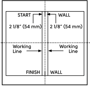
Fig. 2a
Fig. 2b - Open several cartons/boxes of the material. The planks will be marked “A” and “B” on the back (diagram below). Separate the different planks in stacks keeping the edges the same direction (Fig 3). Shuffle the planks in each stack to achieve a more natural look, for installation.
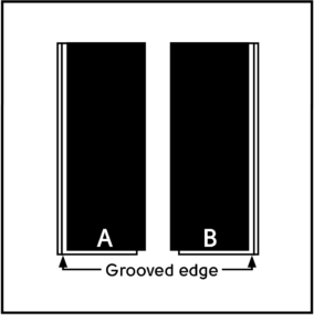
Fig. 3 - Take one “A” plank and one “B” plank and place as shown below. Tilt the leading edge of plank B, slide the joint together and lay flat (Fig 4a & 4b). This is the starting angle. Note: 5 mm spacers are required at all walls or vertical abutments.

Fig. 4a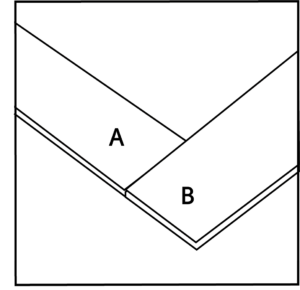
Fig. 4b - Line up the outside corner edge of the “A” plank with the inside corner on the opposite line position (Fig 5).
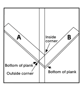
Fig. 5 - Continue installing planks without cutting them, working in opposite directions. Verify that the installed planks are straight on the lines. (Fig 6). carefully tap the plank/tile together flat on the floor.

Fig. 6 - Begin at the ‘Finish wall’ and slide the end joint of a ‘B’ plank into the side of an ‘A’ plank. Slide the ‘B’ plank back into the end of the ‘A’ plank at a slight angle until tight (Fig 7). Note: if there is any drift off the centre line, the product can be moved back and forth across the floor (Fig 7).
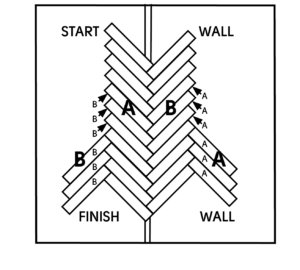
Fig. 7 - Continue installing ‘B’ planks. Repeat on the other side of the row of original ‘B’ planks with the ‘A’ planks. Complete the installation, using the same method whilst keeping the expansion spacers in place and the pattern square (Fig 8).

Fig. 8 - Cutting and installing planks at the walls should be done as follows: Measure and mark the planks as shown in the diagram. The angle for the wall can be determined using an angle finder (see below) (Fig 9).

Fig. 9

2G® is a patented technology invented by Välinge Innovation AB. The 2G® word mark and logo are registered trademarks owned by Välinge innovation AB and any use of such marks is under license.
